TSP with DTM IEC 61850 Virtual Isolation Demo
Introduction
To understand how to load the workspaces in TSP & DTM and how to use the different tools and displays, please refer to the explanations provided in TSP with DTM IEC 61850 Substation Demo
Introduction to Virtual Isolation in IEC 61850
IEC 61850 supports performing tests in a life system with the concept of virtual isolation which consists of:
- A Data Object in LLN0 and optionally in any LN called Mod which can be set to “on”, “blocked”, “test”, “test/blocked”, or “off” for a hierarchy of Logical devices and Logical Nodes. A second Data Object called Beh (behavior) indicates the resulting value and the test bit in the quality flag allows applications receiving a Data Object to determine if the behavior of its LN is in test.
- A Data Object in LN LPHD called Sim that determines whether a device will switch to a simulated GOOSE or sampled values stream if published by a test system.
The workspaces named “IEC 61850 Virtual Isolation Demo” available in DTM and Test Suite Pro demonstrate how the Virtual Isolation concept works by showing all eight combinations of LPHD.Sim and Mod in subscribing Logical Nodes.
The DTM "IEC 61850 Virtual Isolation Demo" Workspace
It is important that the version of the 61850 Virtual Isolation Demo workspace loaded into DTM has the same SCL file as the Test Suite Pro Workspace, so please update DTM if the release version is less than 1.5.0.4549 and update Test Suite Pro if the DTM release is greater than 1.5.1.0.
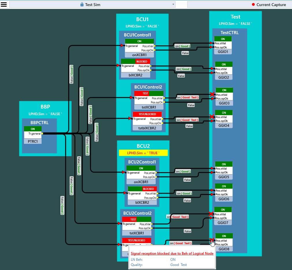
The workspace in DTM is simulating one busbar protection IED (BBP) and two bay controller IEDs (BCU1 and BCU2). BCU1 and BCU2 have each four logical nodes XCBR. From those LNs, each of them is in a different mode: on, blocked, test and test/blocked. BCU2 has LPHD.Sim set to true and therefore accepts simulated GOOSE messages if available on the network. BBP sends a GOOSE message with a trip signal that trips the breakers in the bay controller. As part of the DTM workspace, a fault can be simulated. There is also an IED Test, which subscribes to GOOSE messages from BCU1 and BCU2 with the position and the attribute opOk of all breakers.
The TSP "IEC 61850 Virtual Isolation Demo" Workspace
The workspace in TSP contains a signal flow diagram which visualizes the IEDs and the GOOSE based signal flow. The IEDs indicate the current value of LPHD.Sim and the Logical Nodes indicate the current value of Behavior. Virtual Isolation is shown with an ‘X’ on the signal lines to show the signal is not accepted under the following conditions:
- If the Data Attribute is also available in a simulated GOOSE stream from a Test Device, one of these streams will not be accepted based on the value of LPHD.Sim for the IED
- A Logical Node will not accept a signal if the quality bit test is not compatible with the Behavior of the Logical Node
In Test Sequencer of the TSP workspace, there is an example test plan provided. The following is a basic description of the tests:
- Step 0 verifies the initial conditions and asks the user to publish a simulated message for the IED BBP in the GOOSE Publisher.
- Step 1 verifies the behavior when BBP sends a GOOSE message with a trip with the LN PTRC being in mode “on”. In BCU2, nothing will happen, as BCU2 is subscribing to the simulated message. In BCU1, the breakers in the LN with mode “on” and “test” shall open, the ones with mode “blocked” or “test/blocked” shall not open. However, all LNs shall indicate with the DA Pos.opOk that they would have opened if not being blocked.
- Step 2 does the same but with the LN PTRC set to mode “test”. As a result, the quality of the trip signal from PTRC has the test bit set, and the LN XCBR with mode “on” or “blocked” will not open and Pos.opOk from those LNs will not get activated. So only the breaker with the LN XCBR set to mode “test” will open and Pos.opOk will activate for it and the LN XCBR with mode set to “test/blocked”.